Italian feedback variant
The defrost thermostat is a conventional mechanical thermostat with a group of changeover contacts; it is set for a specific temperature range. This makes the circuit outstanding as compared to the conventional solutions which use simple bimetallic defrost thermostats.
Designations
M - timer motor
The electromechanical timer operating principle is based on rotation of the shaped drum sequencer by the micromotor. The drum periodically switches over the timer contacts. Thus, time is counted down only when the micromotor is powered.C - compressor
The refrigeration unit operating principle is based on physical processes in its pipelines during coolant circulation in them. Circulation is provided by refrigeration unit compressor. Its operation causes intense cooling of the refrigeration unit evaporator.F - fan
Heat exchange between the refrigeration unit evaporator surface and food products inside the refrigerator is provided by the air flow created by the No Frost system fan.R - defrost heater
The moisture in the air, blowing down the intensely cooled evaporator of the No Frost system, gradually settles on its surface as frost. The heater, attached on the evaporator, assures its heating for frost melting and surface cleaning. It is needed to prevent formation of an excessively thick frost layer, impairing effectiveness of heat exchange between the evaporator and air flow.DT - defrost thermostat
Temperature of the No Frost system evaporator must be monitored during automatic defrost, so as to switch off the heater in time. The defrost thermostat is used for temperature monitoring. Its contacts open at a temperature slightly above the frost melting temperature.Interactive Circuit Diagram
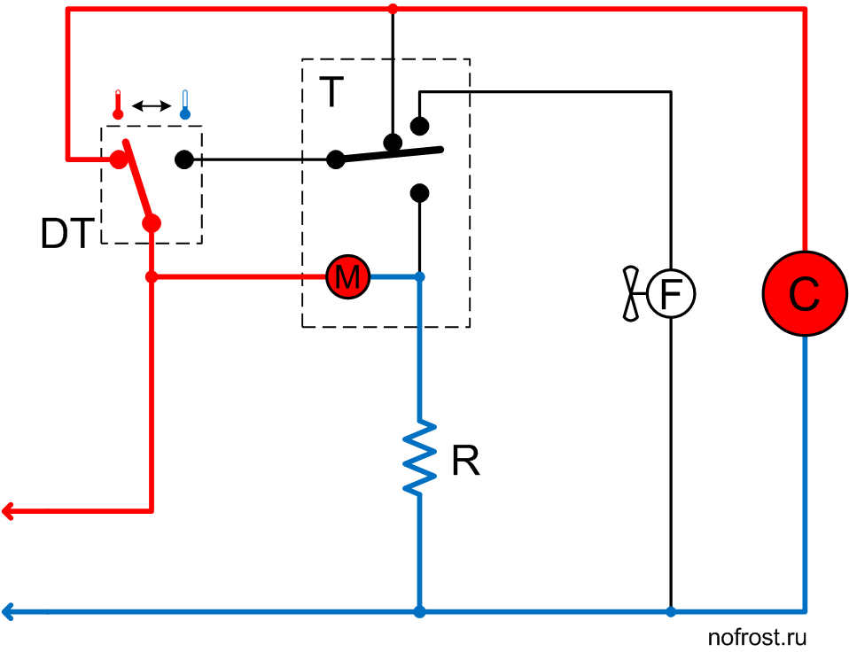
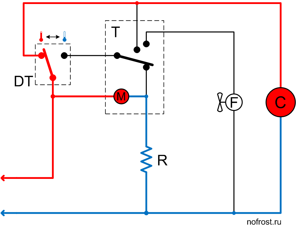
The system is in the mode of initial rapid cooling and the defrost thermostat contacts are set to the position corresponding to the warm evaporator. The compressor is powered via the defrost thermostat, while the fan is de-energized.
The system operates in this mode only for several minutes. Usually this time is enough for sufficient cooling of the evaporator and switchover of the defrost thermostat contacts to the right-hand position according to the diagram, corresponding to the cold evaporator.
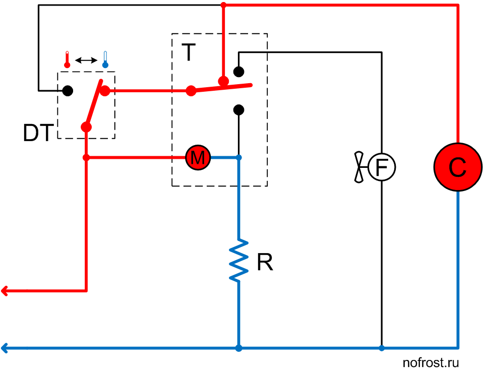
The evaporator has cooled down sufficiently and the defrost thermostat contacts have switched over to the right-hand position according to the diagram.
The compressor is now powered via the defrost thermostat and the timer connected in series. The fan is still de-energized, but the timer will power it up in several minutes.
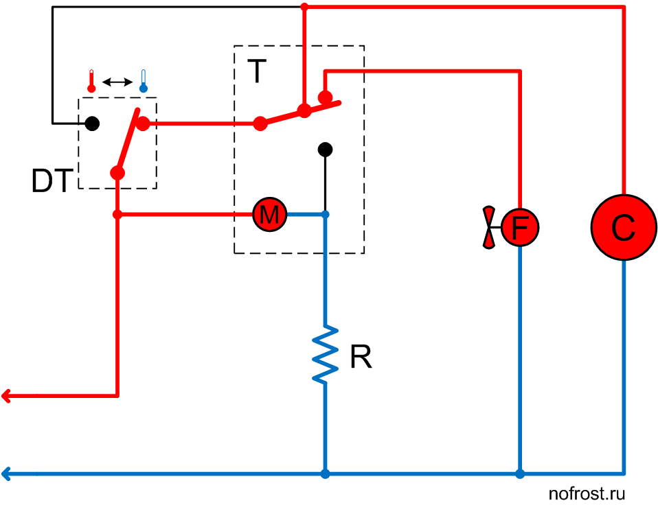
The timer contacts set to a position providing simultaneous power supply of the compressor and fan. It is the main system operation mode, in which it stays for the next few hours, cooling products in the refrigerator boxes.
The timer motor is powered via the defrost heater.
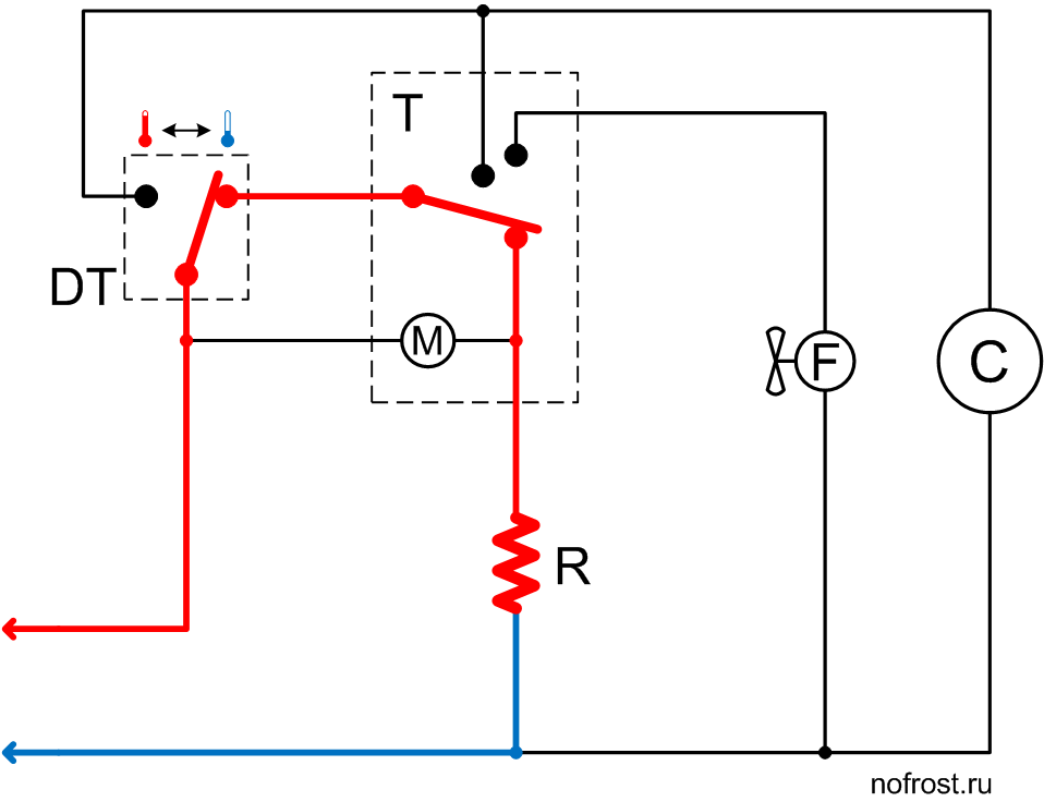
The system has set to the defrost mode. The timer de-energized the compressor and fan and powered up the defrost heater.
Evaporator temperature is low as yet, that’s why the defrost thermostat contacts are in the right-hand position according to the diagram. The timer motor is de-energized. Evaporator temperature slowly rises due to heater operation.
The heater warmed up the evaporator to above the frost melting temperature and the defrost thermostat contacts have switched over, de-energizing the heater and powering up the compressor. The timer motor is also operating. However, the fan is still de-energized.
We see there is no pause. The system activates the compressor right after heater switch-off. While the system operates with the compressor ON and the fan OFF, the cooled evaporator successfully recovers the heat generated during defrost.
The system operates in this mode for several minutes, and then the timer will switch over its contacts.
Conclusion
This circuit is free from some fundamental shortcomings inherent in standard systems.The high-precision defrost thermostat allows more accurate determination of time of defrost heater switch-off, avoiding excessive heating of the evaporator. It is hard to achieve in conventional circuits due to large technologic spread of bimetallic instrument parameters.
Absence of pause before compressor switch-on allows efficient recovery of the heat, generated during defrost, before fan switch-on, while preventing heat ingress in product boxes.
However, such improvements required circuit complication and increased part prices. That’s why this circuit is not widespread.
This circuit was improved in the course of time, and we will have a look at it.